A custom killswitch - case modding

Status
Not open for further replies.

bushwhacker

Posts: 788   +2
Hello

Before i go ahead with the project, i was wondering if i draw it correctly.

This will serves as my custom killswitch to kill the light so it will stop disturbing my sleep while the torrent downloads.

h093bdtmpwa4.jpg


For the switch, I may use lot of wire, due it iwll be bringing up to front.

Thank you.

Plus i think the red one is 12V, which i may need it, so i will add up the light tube ?
 
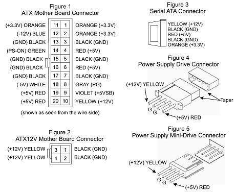
if that picture is of the HDD/optical drive cable or floppy drive cable than the yellow wire is +12v, the red wire is +5v, and the two black wires are ground.
 
also, your switch will work fine as long as the light you want to switch off draws it's power from the +12v line.
 
Okay, 12V it is.

Because, I owns the Aspire X-Cruiser...

THe blue light was very disturbing at night time, i barely get any sleep

So, in addition, i probably plug the front light on 5V and the 12V for light tube

Thanks for your help, KingCody.
 
Perhaps this will help you to figure out that the yellow is 12v and the red is 5v.
20waymolex.jpg
 
Those 2 black wires in your diagram both go to the same ground inside the PSU. So they are essentially the same wire. You can cut those and make them into 1 wire, then install a switch on that one wire.

Basically the 12V goes up one line, and down the ground, same with the 5V. The ground is shared between everything the -12, -3.3, 3.3, 5, 12 all go to the same ground, there are different wires for that ground, but its the same. You can verify this by doing a continuity check between any of the grounds on your system (for 2 12V rail systems this may not be true, but it would be along that common rail).
 
Computer Freak, i hate those switches.
I already have the switches that will be discreet for the Aspire X-Cruiser.

Sngx, thanks for the tip, i will try it.
 
Sngx1275 is correct in that all black wires go to a common ground. I refurb and repair psu's and can tell you than all black wires are soldered to a single ground plane within the psu.
The downside to that is that there are many many routes to ground so that fitting the switch to the ground wont really work.
An electrical charge will always take the path of least resistance.

You should build it exactly to your drawing except for the extra pin on the switch should not be grounded and should be insulated instead.

Having the switch break the yellow (+12volts) will work the best and require the least ammount of work.

I for one would like to see a picture or 2 of the project if you have means to do so.:)
 
Rik said:
The downside to that is that there are many many routes to ground so that fitting the switch to the ground wont really work.
An electrical charge will always take the path of least resistance.
There is no other path to the ground though, the ground has to go through those 2 black wires in his diagram (either that or jump the insulation and hit the case). So putting the switch on that will work. This weekend when I have some time I could probably even prove this, I've got a hacked apart PSU where I ran the different voltage rails to terminals so I could get lots more voltages than the standard ones by wiring to different terminals (for motors and stuff, not sensitive electronics).
 
I uses the break between the 5V and 12V.
The switch itself don't need the ground.

I will show the picture of progress when i purchase a switch to finish the last 5V breakpoint.

If this don't work, i will try sngx's mod instead.


Edited = sngx, i'm still interested of your worklog and pictures for switches.
 
Sorry for double post.

Edited
------

I decided to put up my worklog in here for everyone to see.

Hello guys, I'm back.

Finally got the time to install this. This is pretty cheaps, only if you can find something around that is useful, such as wires. )

Material needed:
Any Female to male molex plugs with 4 wires.
2x switch ( 5V and 12V must be operating separately for a safe reason, so 2 switches will be installed ) plus 4 wire crimps plug
2-4 heatshrink tubes ( You need only about 5cm in length, each)
Solder gun, lead and some flux to melt the lead
4, 8 or 12 gauge wires ( white/yellow, red and black )
A case with either 3.5" or 5.25" bay slot ( That area must be empty )

DISCLAIMER: I do not condone this procedure if your case are under warranty Anyway. The real disclaimer that the pictures itself are large.

Easy mistake to make:
No acid flux for the solder. I did went the long way and did some damages to my solder gun, i have to purchase the new one. I didn't even realizes that acid flux will be a huge help and I also don't even realize that we had one in my dad's basement. Here is the image of it.
It is still alive, but didn't work very well.


This custom killswitch is very easy to make and yet so cheap. You can make this less than a hour.

Steps.
1. Deciding where your killswitch will go. In my case ( bottom of 5.25" bay, below Sony DRU-800A)


2. I went ahead and hacks it up. You will need to break the line connection for the switches. First, i cut the both 5V and 12V line in half, insert the heatshrink and solder it, shrink it. Now it is ready for the switch.
Remember, your favor on switch is different than mine. I chose this so it can hides inside the case door well. ( I made the mistake on the wiring, but they wired in properly, but not color. Notice on the left is red, 5V. On the right, yellow is 12V. Notice the switch plugs? Ok, cool. Let head on.) After you are done with this, please test the switches before install it inside the case.


3. You will need to mod your bay cover. Start with small drill bit, increase by 4 size each time to biggest bit ( The one that fit snugly on your switch) I went ahead and mod it. Installed perfectly.


4. You need to notice that this killswitch need to operate separately, particular the reason of the add-on lights in the future. If you don't have enough, you can just run it off between the hard drive. No harm done.


5. Install the bay and you are done!


I had the good sleep and wakes up to see the download finishes.
 
Status
Not open for further replies.
Back