Nvidia investigating cases of melting RTX 4090 power cables, RDNA 3 won't use 12VHPWR

"Those looking to upgrade without replacing their ATX 2.0 PSUs can use adapters bundled with the cards connecting three 8-pins or four 8-pins to one 12VHPWR cable."

Question: Unless I'm very mistaken, doesn't a single 8-pin have a 150W limit? Wouldn't that imply a converter cable that uses just three 8-pin connectors would result in at least one of those 8-pins exceeding that limit (if total draw of the GPU is >450W)?
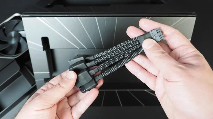
Some of the power is supplied via the PCI Express slot, up to a maximum of 75W. So, in theory, the slot and three 8-pin connectors can provide 525W.

However, most cards don't go near the 75W limit on the PCIe slot, typically only hitting around 50W or so. That's why 4090 cards with TDPs higher than 450W (e.g. MSI's Suprim Liquid X that's 480W) come with a four 8-pin adapter.

Edit: Cards will distribute the current demand across the various supply channels. Below is my RTX 2080 Super at full power:

2080_super_max_power.jpg

Here you can the PCIe slot is at 71% capacity, the 6-pin connector is at 83% capacity, and the 8-pin at 91% (board sensors are a little bit on the rough side, so treat the figures as estimates, rather than concrete values).

So if one assumed the same loads exist on a 450W card with three 8-pin connectors, then each of the latter would be at 89% capacity.
 
Last edited:
What's a little puzzling here is that I don't recall (but more than happy to be shown otherwise!) that the 3090 Ti, which also used the 12VHPWR connector (via a three 8 pin socket adapter), showed no signs of burning out connectors. That's a 450W card too.
That's easy to explain. The 3090 is shorter height-wise and the power connectors stuck out of the card at an angle, whereas the 4090 connector sticks out at a straight 90 degree angle. The pins failing is likely due to mechanical stress. The unprecedented height of the 4090 means you HAVE TO put an extreme bend radius on the power connector in order to close your side panel since virtually no cases available today are wide enough to support a safe bend radius with a 4090. You're almost forced to mount the card vertically.

Jay actually covered the cable in more detail in his first video on ATX 3.0:


30 total insertions is just really low for a cable spec.
 
amps is Watts divided by Volts which is 50 amps or Volts X Amps equal watts

At 120v 600 watts is 5 amps
as graphics cards use 12v it's 50 amps which needs a thick pipe to supply.
With 0.1 A a human heart stops. So, to have 50 A feeding your graphics card is just insane.
 
That's easy to explain. The 3090 is shorter height-wise and the power connectors stuck out of the card at an angle, whereas the 4090 connector sticks out at a straight 90 degree angle.
That's certainly true for the Nvidia FE models, but one of the first melting complaints on Reddit was for an Asus TUF. Both the 4090 and 3090 Ti cards, in that line, have straight 90 degree 12VHPWR connectors on the PCB:

4090: https://dlcdnwebimgs.asus.com/gain/3b0f0aef-20c9-407c-9a72-c6394dcb51a7//fwebp
3090 Ti: https://dlcdnwebimgs.asus.com/gain/be1e2903-4e6e-47c8-aeb2-5b3f2f5061a1//fwebp

The 4090 model is 9.8 mm (0.39 inches) higher than the 3090 Ti, which doesn't seem like it should be enough to cause additional stress, but it may well be if the Asus-supplied adapter is of cheap quality.

30 total insertions is just really low for a cable spec.
For a mobile phone? Sure. For a graphics card? I'd say no, it's fine. The typical user isn't going to be unplugging the card more than 30 times in its lifespan.
 
Looking again at old vs new connectors for GPU's I realize that old 8 pin had only 3 wires for + and 3 wires for - and was rated at 150W.
The new connector is 6 wires for + and 6 wires for - and with old connector this translates to 300W.
The wire gauge dont look too different on both, the only difference is the pins are smaller on new one and also the contact surface and pressure.
My 2 cents is that this new 12pin connector should not be used for more than 300W sustained.

74775_01_this-is-an-even-better-look-at-nvidias-new-12-pin-power-connector.jpg


In general rules for electric circuits, for wires and couples the recommended max usable power should be 3/4 from the circuit power.
This translates to 400W max peak power and nominal 300W for old and new cable.
 
Way back on Socket A days one friend of mine decided to change the thermal paste. When reinserting the cooler in those damn clamps one didn't lock all the way up.
He started the PC and had to go out, someone on front door. Guess what in 5 minutes his room was on fire. And after all investigation police and firefighters concluded the PC was the cause.
That was back in the days AMD cpu's didnt have the thermal shutdown like now.
Yes. It appears history is repeating itself and the PC power supply committee never learned the lesson.

In the socket A days, I had a dual socket A board. That was before ATX power supplies were a thing and it was IBM PC AT/XT power supplies that had MB connectors I cannot even find a picture of on the net these days. With my dual socket A board, the MB connectors from the power supply got charred - obviously, they could not handle the current and thus the ATX power supply was born. My solution, at the time, was to cut the connector off and solder the wires from the power supply directly to the MB connector pins.

Yet it seems - here we are again - which brings to my mind this quote:

“Those who fail to learn from history are doomed to repeat it.”

― George Santayana

To me, its really interesting that modern day engineers would make such a basic mistake. A question I have though, is was the problem the result of nVidia engineers exceeding the limits of those connectors, or was it the power supply committee that failed in their task?

Anyway, perhaps this will go down in PC history as yet another epic fail. :laughing:
 
But within the PC, the PSU converts the AC wall power to DC and steps its voltage way down, to 12V and below, where semiconductor junctions are far, far happier. So, on-board wattages will be at those voltages.
They use systems that can record the current draw the various supply pins/cables. Sites such as TechPowerUp use these for their power charts in GPU reviews.
Thanks gents, but the truth is I am probably never going to get exactly how it's done. Well, not with my current level of technical savvy.

Take my laptop as an example. It has a 175 watt 3080 and an 80 watt 5900HX.
When I ran Cinebench and 3DMark at the same time my total draw was 290 watts, which makes sense seeing as that also included the draw of the 2K display.

So anyway, if I am getting it right, a GPU rated at 600 watts means draw from the power supply after it does its thing, and not necessarily from the wall.
Am I even close?

It's kinda hard to overblow something like this. That's like saying that the Gigabyte PSUs that poofed were overblown by Steve Burke. If the connector melted, it melted. It might not be a fire hazard but it's still pretty damn bad, especially considering that it cost US$1,600 for this melting privilege! :laughing:
No AA, what I meant by overblown was kind of like the "AMD drivers still suck" thing when it's probably coming from people that don't even have an AMD GPU.
 
So anyway, if I am getting it right, a GPU rated at 600 watts means draw from the power supply after it does its thing, and not necessarily from the wall.
Yes - while remembering that draw from the wall envelopes and defines ALL the power that will be used throughout the system. Some will be dissipated in the PSU as it converts high voltage to low. Some in the CPU, some in the fan motors etc. And some in your 600W (usually less ofc) GPU. All of those added together = draw from the wall.
 
Last edited:
Igor's Lab has a very good write-up and pix. It may be an issue only with adapter quality and thus fixable by making those far more carefully. However, cramming so many big wires in such a small space is an inherent difficulty, and not only because of the crucial strain relief issues. IMHO the PCB space saved by going to the tiny connector isn't worth that. But, yet again, I wasn't consulted.

 
No AA, what I meant by overblown was kind of like the "AMD drivers still suck" thing when it's probably coming from people that don't even have an AMD GPU.
Ah ok, now I understand. Thanks for the clarification! I really was kinda confused (not that it's hard to confuse me....). :laughing:
 
No, it's properly referred to as "Frankly Speaking" or "A Reality Check".

If someone does something galactically dumb, are you going to cheer them on for fear of "purchase shaming"? I assume that he's new to this and made a beginner's mistake but it was still a bad decision. People generally don't get to make a bad decision and then complain about it to others without having to eat their fair share of crow in the process. Note that the only person who agrees with you is the person who committed this titanic blunder. Everyone else just read your post thought "Pfft! Yeah, ok there buddy!" and moved on. I figured that you were at least entitled to an explanation so here I am giving it.

Welcome to the world, try not to burn yourself. :laughing:

Not exactly what one would expect from one of the most expensive video cards ever released, eh? :laughing:

It's just mind-boggling the things that weren't considered imperative back then, eh? 🙄

Gamers Nexus has some fancy equipment for just that purpose but I have no idea how it works. All I know is that it cost them thousands.

They should have just used the four PCI-Express connectors. That would've been A LOT simpler (and evidently, more reliable too).
Naaaah, you're a know-it-all.
 
I really don't see the point of these oddball connectors. It's just another proprietary thing from nVidia to make the noobs think that it's special.
Its a part of the ATX3.0 standard, and was introduced specifically to carry more more power lines, higher voltages, and higher currents. nVidia is just the first to use it.

As I said elsewhere, I would not be surprised if either their a mechanical flaw in these new connectors (most likely, imo, they're new; manufacturers don't even know where the corners are yet, so they can't exactly deliberately cut them); or the designers of this connector really did do a thorough job, but management went "huh, that's expensive, but if I do it like [this] instead, its not as expensive".
It would make sense if it were something that can't be done with existing PCI-Express supplementary power connectors but it isn't. It also can't be less expensive when PSUs have the necessary male connectors already instead of nVidia having to provide one.
 
The 4090 model is 9.8 mm (0.39 inches) higher than the 3090 Ti, which doesn't seem like it should be enough to cause additional stress, but it may well be if the Asus-supplied adapter is of cheap quality.
Having almost a cm more clearance is very valuable when your side panel is literally pressing in on the power connector. Like when you overfill a suitcase and end up having to put your whole body weight on it just to lock it closed. It's really far from ideal. That being said I hear CableMods is making a higher quality right-angle 12VHPWR connector which should basically solve this whole issue.

[SIZE=13px]For a mobile phone? Sure. For a graphics card? I'd say no, it's fine. The typical user isn't going to be unplugging the card more than 30 times in its lifespan.[/SIZE]
One typical user on a brand new card, 30 is okay maybe. But what about the used market? You have no idea how many times it's been plugged and unplugged. Perhaps it's been on the shelf for a while so someone plugs it to test if it works. Well that's one more cycle gone. And in a perfect world everything just works, but in the real world things go wrong and you need to troubleshoot. Say you seem to have a graphics problem, is it your GPU? Your motherboard? Your power supply? It could be any combination of the above and you end up needing to plug and unplug components sometimes several times to rule out various hardware issues or hardware / software incompatibilities. Again, 30 is way too low a limit.
The RX580 is almost six years old but it's still a perfectly decent card for 1080p gaming. But if it had a connector with a 30 cycle limit I'm fairly sure there would be far fewer of them on the used market today.

But why does a $1500+ graphics card today have such a fragile power connector when no other card before it does? I wouldn't just shrug and say it's fine because I personally don't see myself plugging and unplugging the card more than 30 times. That's the road to planned obsolescence and even more e-waste.
 
Depending on what manufacturer is used, the standard PCIe power connectors can also have a mating cycle rating of 30 - for example, Molex Micro Fit 3.0 have a typical limit of 30, whereas their Reduced Mating Force models have a limit of 250, due to inclusion of a lubricant. Guess which ones graphics vendors use to keep manufacturing costs down to an absolute minimum?

Add-in graphics card connection systems aren't designed to be handled like USB devices. The PCI Express slot itself can be rated from 50 to 200 cycles (PCIe riser cards are 30), whereas external PCIe connectors are up to 250 cycles.

The mating cycle limit isn't the issue here. It's a combination of insufficient testing, shoddy manufacturing, and penny-pinching by AIB vendors.
 
I'll posit the cable engineering is the root cause rather than the manufacturing. While the soldering may not be the tidiest, it is okay given the limitations of the environment. And that could well be nVidia's choices.

The choice of four-to-one adapter creates a terrible choice of join. A three-to-one adapter would've been far more compatible.

But the biggest problem by far is the lack of any strain relief. And on that note, arguably, the plug itself is at fault for having no built-in strain relief.

All that said, soldering shouldn't have been employed at all. Crimp connectors exist for a reason.
 
It would make sense if it were something that can't be done with existing PCI-Express supplementary power connectors but it isn't. It also can't be less expensive when PSUs have the necessary male connectors already instead of nVidia having to provide one.
When it comes to electrical power, a dedicated solution is superior to one cobbled together with adapters or by adding more cables.
When you use multiple cables together, it becomes possible for you to get differentials across what should be identical potentials (Two connectors, each with a 5V line, but one is really 5.1V and the other is at 4.9V, creating 0.2V difference - for example)
When you use an adapter, you increase the number of places for something like this to happen. You want to decrease the number of connectors in a system, not increase them, if you want to increase reliability.
 
When it comes to electrical power, a dedicated solution is superior to one cobbled together with adapters or by adding more cables.
Are you even reading your own words? All this connector does is take the existing PCI-Express supplemental power cables and merge them into a smaller connection point. It literally ADDS A STEP with TWO EXTRA CONNECTIONS that wouldn't otherwise be there!

Are you aware that you're saying that cobbling together is bad as a defence for something that's cobbled together?
When you use multiple cables together, it becomes possible for you to get differentials across what should be identical potentials (Two connectors, each with a 5V line, but one is really 5.1V and the other is at 4.9V, creating 0.2V difference - for example)
Holy Jesus, I guess you'll need pictures to point out just how absurd what you're saying is:
small_geforce-rtx-4090-12vhpwr-adapter.jpg

Do you SEE how it uses the four PCI-Express supplemental cable connectors? That "variance" that you're trying to gaslight me with would STILL be present even with this connector. The only difference being that the circuit merges the four connectors into one outside of the card instead of inside it. There is literally no difference here except for this one extra adapter, an adapter that serves no purpose except for maybe the noobs who don't want four wires visibly attached to their card for "visual reasons".
When you use an adapter, you increase the number of places for something like this to happen. You want to decrease the number of connectors in a system, not increase them, if you want to increase reliability.
And nVidia is doing JUST THAT, using an EXTRA adapter! Are you for real?

Do you work for nVidia or something? I'm not someone you can just gaslight there buddy. I've been building PCs since 1988 and there's nothing that I don't know about it.
 
They should have just used the four PCI-Express connectors. That would've been A LOT simpler (and evidently, more reliable too).

That's a ton of space being used up on a card for four of the 8 pin PCIE connectors. The founder's edition and AIB cards both would have been bigger with that many 8 pin connectors.
 
Are you even reading your own words? All this connector does is take the existing PCI-Express supplemental power cables and merge them into a smaller connection point. It literally ADDS A STEP with TWO EXTRA CONNECTIONS that wouldn't otherwise be there!

Are you aware that you're saying that cobbling together is bad as a defence for something that's cobbled together?

Holy Jesus, I guess you'll need pictures to point out just how absurd what you're saying is:
small_geforce-rtx-4090-12vhpwr-adapter.jpg

Do you SEE how it uses the four PCI-Express supplemental cable connectors? That "variance" that you're trying to gaslight me with would STILL be present even with this connector. The only difference being that the circuit merges the four connectors into one outside of the card instead of inside it. There is literally no difference here except for this one extra adapter, an adapter that serves no purpose except for maybe the noobs who don't want four wires visibly attached to their card for "visual reasons".

And nVidia is doing JUST THAT, using an EXTRA adapter! Are you for real?

Do you work for nVidia or something? I'm not someone you can just gaslight there buddy. I've been building PCs since 1988 and there's nothing that I don't know about it.
What I said: using adapters is inferior to a dedicated solution
What you read, apparently: nVidia is right to use adapters

In fact, re-reading all your comments, you seem to be confusing the difference between "connectors" and "adapters". The 12-pin on the GPU is the connector. The picture you included is the adapter.

This new 12-pin connector is not nVidia's creation. Its a part of the ATX3.0 standard. The adapter is nVidia's creation, and is not part of the ATX3.0 standard. And if you look at the other thread, you'll see the issue is almost certainly poor design (too few wires going into the 12-pin connector, going to too many pins; thin pins) mixed with poor manufacturing (really poor soldering; cold solder joints) of the adapter. Basically, exactly what I said it likely was in my original comment.

The adapter nVidia provided is obviously trash. That doesn't mean no adapter could ever work (see; Cable Mod's 12-pin adapter for a successful implementation). It also doesn't mean that any adapter is better than an ATX3.0 PSU that has the new 12-pin cable as a part of its standard kit; a compliant PSU with dedicated 12-pin cable will be superior to any adapter/non-compliant PSU combo.
 
Back