
In today's world of AI and machine intelligence, it sometimes skips the mind that the primary end-user of many computing systems are … human. And, as humans, we are far from perfect – not just in our judgments, but also in our senses and perception of the physical world around us.
Early programmers and hardware architects realized this instinctively: computers do not need to be exact in everything they do. There are many instances where approximate computing techniques or heuristics can go a long way, leaning into the fact that neither humans nor their technologies need to be picture-perfect to provide an enjoyable experience. That beautiful balance between precision and approximation has long been the engine of progress, powering some of the most ingenious ideas in computing.
Enter JPEG, a format so familiar it's practically invisible. It's one of the quiet marvels of modern engineering – an image compression standard born from equal parts math, psychology, and aesthetic intuition. JPEG doesn't just shrink images; it encodes an understanding of how humans see.
At its core, JPEG is a lossy image compression technique – a balancing act between file size and visual fidelity. However, achieving this required a fascinating blend of human perception, elegant signal processing, and clever engineering prowess.

At a high level, JPEG is a lossy image compression technique that meticulously balances file size with acceptable visual fidelity. However, achieving this required a fascinating blend of human perception, elegant signal processing, and clever engineering prowess. Decades later, we're still living with the ripple effects – right down to the way we talk about AI itself, leading to analogies like, "ChatGPT is a blurry JPEG of the web"!
In this article, we'll unpack all the magic that goes on every single time you save or load a JPEG image. If you haven't been enlightened yet about how JPEG works, then let us begin at the source: human perception of light!
Human Perception and Computing
You probably don't think about it much, but all our interactions with technology are through our physical senses. Your hands tap, swipe, and scroll; your ears tune into the subtle ping of a notification or the hum of a video call; your eyes scan a glowing field of pixels that somehow turns into text, color, and cat videos.
These senses form the front line of human – computer interaction – the invisible interface between biology and circuitry. Each modality has evolved alongside technology itself, shaping how we design and experience the digital world. The magic lies in how engineers and designers have learned to exploit the quirks of perception – those little physiological shortcuts – to make machines feel intuitive, even human.

Take vision, for instance. Our eyes aren't flawless cameras; they're messy biological sensors with limits and blind spots. When a display doesn't refresh quickly enough, the illusion collapses – you see "tearing," a split-second break in motion that reminds you the pixels are faking continuity.
Scientists can even quantify what "fast enough" means: around 30 to 60 frames per second is typically smooth enough to fool the eye, and most of us can't tell the difference beyond that, at least in everyday use.
Another useful metric when it comes to eye sight is brightness, typically captured in nits or "candela per square meter". A "candela" is Latin for "candle." So one candela is equal to the brightness of a single average candle.
When you add in square meters, you can measure the luminous intensity spread out over a surface. One "nit" is the brightness of one candle shining onto a surface that measures one meter across and one meter down. For reference, an iPhone 17 boasts 1,000 nits (typical) brightness, can reach 1,600 nits in HDR content, and achieves 3,000 nits of peak brightness in outdoor conditions.
Ok, let's get back to images and JPEG: by understanding some of the physical limits of the human eye, we can use some of this information to quantitatively and aggressively compress the information in a picture, without the perception of quality degradation. As you might know, JPEG is a lossy compression format. This means that certain information is thrown away (in a calculated manner) in order to improve the compression ratio while seeking to minimally disturb visual perception.
JPEG and JPG are exactly the same! The only difference is that the latter is a three letter acronym, which was required at the time because Microsoft file extensions could only support three letters (such as .doc, .ppt, or .jpg).
Other file systems, such as in Linux, did not have the limitation. For more information check out our File System Explainer article.
Some other image formats, such as PNG, are lossless. This means that no information is lost during the storage of an image, which typically results in a much larger image footprint. As an example, an image with dimensions 2592 x 1944 saved in PNG format would use up about 15 megabytes, while the same image saved in JPEG would be about .75 megabytes, roughly 20 times smaller and practically unnoticeable visually to the human eye.
When JPEG was standardized in the early 1990s, it was more out of necessity than anything else. The BMP file format developed by Microsoft produced images that were relatively large and the computers of yesteryear would have trouble saving, loading, and transferring so many bits of information in the early days of the web.
If only there was a medium and technique which could produce images with very similar perceptual quality, but use only a fraction of the bits…
How Does JPEG Work?
Since JPEG is a lossy compression format, the key question we want to ask is, "What information can we safely discard?" This is the key behind being able to get a 10x-20x compression ratio, without a noticeable quality degradation.
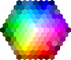
Let's begin with a visual challenge: What are the colors of the tiles marked as A and B in the image below?

Your answer might be along the lines of "A is a darker shade of color than B." However, these two tiles are exactly the same color!
Scientists have been studying this supposed optical illusion for some time, and have developed models to try and explain the phenomenon. In particular, scientists have found that the human eye is more sensitive to brightness than it is to color. And this is where the JPEG compression scheme begins!

Introducing YCbCr
A picture is composed of many pixels, and each pixel is encoded with three values: a red, a green, and a blue value, summarily known as an RGB format. The choice or red, green, and blue as the basis of colors is also physiologically selected: you can represent nearly all other perceivable colors using a mixture of these three primary colors, and the human eye is also good at picking up and interpreting these colors (as well as the spectrum they create).
If we are to use 8 bits (i.e., 1 byte) to represent each color (R, G, and B), that means we need 24 bits per pixel to encode color, and can represent a total of 256 x 256 x 256 possible colors in each pixel (a little over 16 million combinations).
To select a percentage of "red" for a pixel, you would select a number between 0 and 255. The larger the number, the brighter it is. Thus, in this representation, (0, 0, 0) can be used to encode "black", and (255, 255, 255) can be used to represent "white." Different values in-between for the red, green, and blue components can navigate the spectrum of colors in this format.
While the RGB color format is helpful to digitize colors, we want to take advantage of the insight that human eyes are more sensitive to brightness in order to compress an image. To that end, let's use an alternative encoding, called the YCbCr format.
The YCbCr format is also composed of three numbers, but helps capture different information. The "Y" stands for luminance (or "luma" or "brightness); the Cb stands for "chroma blue"; and Cr stands for "chroma red". Effectively, this format is a formulaic mapping from the previous RGB format to an alternative format that explicitly captures brightness and color information!
If you are wondering, "where did green go?", well it's still there! You can think of chroma blue as a ratio/contrast of green to blue in the pixel, and chroma red as a ratio/contrast of red to green. Just a little clever math to keep all three colors: nothing lossy here (yet)!
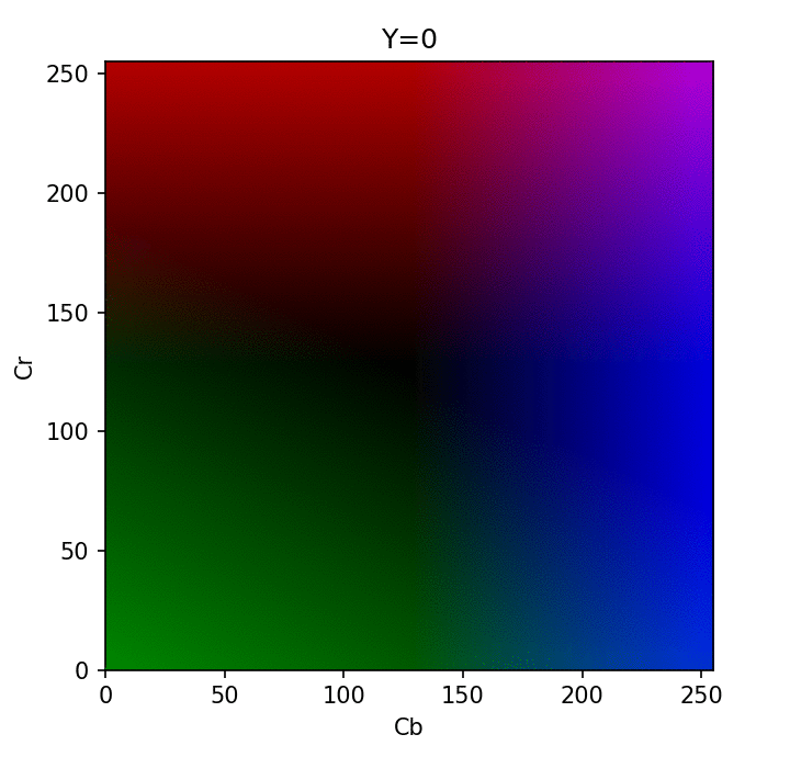
Visualization of different Y in YCbCr format - credit
Using the YCbCr format, we now have direct access to the brightness component which is more critical for our eyes to perceive best. With this separation, we can now perform the first step of JPEG compression, which is "chroma subsampling": reducing the color component deterministically (using sampling) while keeping all the luma information that our human eye puts more importance upon.
Chroma Subsampling
Time to judiciously get rid of some information in images!
Technically, chroma subsampling is an optional component of the JPEG standard. The idea is to throw away information by sampling color information of pixels.
According to the standard, the options are
- keep all color information
- throw away half the information (typically done for images)
- throw away a quarter of information (typically done for video, and the similar MPEG compression format).
To perform chroma subsampling, you take a block of pixels (for example a block of 8x8) and extract the color components (Cb and Cr). For each color component, you take a subgroup of 2x2 pixels, and convert them all to one color. Essentially, you are sampling certain colors at a small granularity, and extrapolating that information to nearby pixels.
For example, you can take the average of the 2x2 pixels, and then apply that average to each pixel.
Alternatively, and as the JPEG standard uses, you can select the top-left pixel, and apply that color to the other 3 pixels in the 2x2 block.
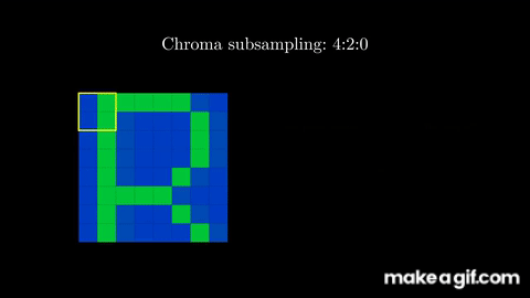
Effectively, we began this step with three channels (Y, Cb, and Cr), and ended up keeping the information intact in one full channel (the brightness component, Y) while reducing the resolution of the other two channels (Cb and Cr) by a factor of four. In other words, we went from 3 full channels to 1 + ¼ + ¼ = 1.5 channels, meaning we're now effectively using 50% of the data of the original image!
If we decided to sample even more aggressively (for example, averaging Cb and Cr over a 4×4 block instead of 2×2), then we'd be reducing the chroma channels by a factor of 16 instead of 4 – resulting in roughly 1 + ¹⁄₁₆ + ¹⁄₁₆ = 1.125 channels, about 37.5% of the original data, or roughly a 2.67:1 compression ratio.
This is only the first part of the JPEG compression scheme. Next up, let's talk about how we can convert our brightness and color information into signals, to throw our mathematical arsenal at it for compression.
Images as Signals
A little imagination here (followed by some foundational math) can help us think about images as signals. We want to convert an image from the spatial domain to the frequency domain.
If we were to take a row of pixels in an image and plot their pixel values, we can effectively have a visualization of their color as a signal of points. Since each pixel is a value between 0 and 255, the following image can help intuitively describe this step.

By looking at this plot, we can label a rapid change between pixels as a high frequency signal, while a slow change between pixels as a low frequency signal.
Classifying signals as high or low frequency allows us to take advantage of another human perceptual phenomenon: the human visual system is less sensitive to higher frequency details!
What is more: typically, most pictures/photos that are taken have more low frequency components rather than high frequency components. Thus, we can take advantage of these observations to cleverly get rid of high frequency parts of an image!
But how? …
Discrete Cosine Transform
To pull this off, we'll need to perform a discrete cosine transform, or DCT. Conceptually, our objective with this step is to transform a set of pixel values (in the spatial domain) into a "sum of sample points from cosine waves" (i.e., the cosine, or frequency, domain).
The math is actually quite elegant to pull this off, but let's focus on intuitively explaining what the DCT is and how it is applied for the JPEG format.
Let's start with the domain itself: why cosine? There are a few reasons why we chose to use the DCT for JPEG, with both theoretical and practical considerations. A cosine wave has a couple of parameters that can be used to encode information: There is the frequency of a cosine wave (to capture the how often pixel values change). Second, there is the amplitude of the cosine wave (i.e., can be used as a weight for a particular cosine frequency). And third, there is a shift up and down in the cosine wave (which can be used to encode pixel brightness).
Using these three parameters, we can capture pixel information in an alternate perspective (the cosine domain) with nice mathematical properties. The most relevant property is that it has a high degree of spectral compaction relative to other domains (e.g., the Fourier Transform).
Recall how we mentioned above that images typically have a large imbalance between high frequency and low frequency information, and the human is more sensitive to low frequency information? The DCT "naturally" puts the information about low frequencies together, and separates them easily from the high frequencies (which we can subsequently compress aggressively).
The DCT isn't necessarily the fastest or best, but practically came to adoption because IBM had the patents for many of the other schemes.
The DCT isn't the only transform that could work for the JPEG compression scheme. In one of the earlier works on JPEG, an evaluation of different transformations to identify which was the most efficient showed the the DCT was pretty good overall, both at capturing low/high frequency information, and was also quick to compute. The DCT isn't necessarily the fastest or best, but practically came to adoption because IBM had the patents for many of the other schemes. Thus, it's openness was a large feature for its incorporation in the standard.
To go from the spatial domain of an 8x8 block of pixels to a corresponding 8x8 block in the DCT domain, we want to capture the DCT coefficients. Effectively, we want to represent the 8x8 signal using a set of 64 cosine waves - the DCT helps calculate how much each cosine wave contributes to the entire block.

2D DCT "set" of cosine waves.
In this 2D space, the top left corner of a DCT will capture the low frequency information, and the bottom right will capture the high frequency information. Since the values in each of the 8x8 matrix blocks is used to encode this information, larger magnitude values in the DCT mean that a particular cosine component is large, and a smaller magnitude value means that a particular cosine component is small. Using our intuition that low frequencies are generally more prevalent, we expect the top left corner to include larger values, and the bottom right corner to include smaller values.
As a basic example, let's convert the following black-and-white image into its DCT coefficients.

First, we would obtain the value for each pixel, which would be a number from 0 (black) to 255 (white). We then subtract 128 from each pixel, to center it around 0. Finally, we calculate the 2D DCT coefficients, using the mathematical formula.

You can notice that the top left corner contains larger magnitude values, which correspond to the low frequency components in an image, while the bottom right values are much smaller in magnitude. We will take advantage of this distribution in the next two steps of the JPEG algorithm: quantization and encoding.
For a more in depth formulation on the mathematics behind going from pixels to DCT coefficients, check out this video with nice visualizations to help build stronger intuitions.
We note that the DCT is still precise, and going back and forth from pixels to the DCT itself isn't dropping any information. The next step, quantization, is where we can do some strong compression to reduce the high frequency bits of information.
Quantization
Quantization is a fancy term which involves mapping a large set of values into a predetermined, smaller set of values, typically involving some rounding and/or scaling. A simple analogy can be made to rounding: for example, instead of focusing on the smaller number of cents in a product ($1.99), you may just round to the ballpark full dollar amount ($2).
If you perform this on a large ledger of values, you will essentially throw away all information about cents, but capture a "close enough" representation via rounding to the nearest dollar amount. Subsequently, you can compress the dollar information more efficiently then having to deal with all the undesired cents granularity.
In the context of JPEG, we want to figure out a method to "throw away" some of the high frequency information by attenuating their effects, while maintaining the low frequency information.
The DCT makes that very easy for us to do, since it puts the similar frequencies nearby in the 8x8 matrix that it produces! All we have to do then is divide each element in the 8x8 DCT by the corresponding value from an 8x8 quantization table, and then round it to the nearest whole number.
The quantization table consists of multiple quantization matrices, where each matrix can be thought of as producing a different quantization scale (more or less compression). These matrices have been somewhat hand-tuned based on the perceptual results at the tail end of the JPEG image compression scheme.

Effectively, once you divide the DCT by the quantization matrix and round to the nearest whole value, a bunch of the high frequency values (in the bottom right of the DCT) become zero.
On the other hand, the low-frequency values (in the top right of the DCT) include various values, signifying their significance in the final information-retraining workflow of the JPEG compression algorithm.

The same quantization matrix is also used when decoding the JPEG image. As you can see, this is the lossy step, since multiplying anything by zero will keep it zero. Thus, you effectively got rid of certain high frequency information altogether, and yet the compression technique is still barely noticeable to the human eye.
Last but not least, you can perform quantization on both the luma and chroma DCTs - however the quantization tables are typically much more aggressive for chroma. As discussed earlier, this is to preserve the luma component since the human eye is more attentive to brightness, but you can still get away with some quantization without too much perceptual loss. A nice simulator here allows you to play with quantization and see its effect on final image quality.
Run-length Encoding and Huffman Encoding within JPEG
With a quantized DCT, most values in the matrix are now zero. This lends itself to another cool technique to encode all the useful values efficiently, called run-length encoding.
The idea behind run length encoding is that you can encode a long sequence of numbers by measuring the frequency of how often numbers show up consecutively. This technique exploits sequential redundancy (of zeros) to compress efficiently.
To do this, the JPEG algorithm organizes the digits in the quantized DCT in a zigzag manner, to maximize the number of zeroes at the end of the sequence.

Then, all we need to do is incorporate the count of each number in the sequence. For example, the above sequence would produce the series:
-24, -2, 0, -2, -1, -3, 1, -2, 0, -1, 0, 0, 1, 0, 1, 0, 0, 0, 0, 0, 0, 0, 0, 0, 0, 0, 0, 0, 0, 0, 0, 0, 0, 0, 0, 0, 0, 0, 0, 0, 0, 0, 0, 0, 0, 0, 0, 0, 0, 0, 0, 0, 0, 0, 0, 0, 0, 0, 0, 0, 0, 0, 0, 0
Instead, we can compactly write it as:
{ -24, -2, 0, -2, -1, -3, 1, -2, 0, -1, 0, 0, 1, 0, 1, (0, 49) }
As you can see, now instead of storing 64 values for the 8x8 block, we only needed to store 17 values.
But wait – there's more!
JPEG actually does something a little more complex to get even more compression out of the information we have. Specifically, it converts each sequence into a triplet consisting of 1) the number of zero's preceding a value, 2) the number of bits needed to encode value c, and 3) the coefficient value.
What makes this representation useful is that there are certain triplets that appear more often than not, statistically based on all the images out there. With that in mind, we can optimize the common triplets using fewer bits (a mapping), such that these frequent triplets are represented efficiently.
Intuitively, this is like representing a sequence of 8 zeros "0 0 0 0 0 0 0 0" with the letter "A", while a less frequent pattern like "0 57 6 2 0 0 4 1" might just need to be encoded as is. As you can see, "A" is a single value mapping the frequent case of back-to-back zeros, while a more nuanced pattern might still need to encode all 8 digits with more "characters". The idea is that a singular "A" will appear enough while the un-common pattern will not, so on average you come out ahead on the compression.
This simplified idea is called Huffman Encoding, and the JPEG standard combines it with run-length encoding for quite efficient compaction of the quantized DCT matrix. This step also is not lossy, as it can precisely reproduce the quantized DCT precisely – but it benefits immensely from the quantization step since quantization helps produce many zeroes to efficiently group up together.
Decompression
This step is quite straightforward: it involves the inverse of all the preceding steps to decompress a JPEG image, typically when you want to view a saved file.
Decompression involves re-interpreting the Huffman/run-length encoding to produce the quantized DCT coefficient matrix, multiple by the quantization matrix to get back to the "normal" DCT matrix, calculate the inverse 2D discrete cosine transform, and then add 128 to each entry in the matrix.

The final result will be a very similar image, but with some subtle differences as this is a lossy compression scheme after all. However, this is just an 8x8 image - a real image would be much less visibly different, and is a big reason why JPEG compression is so effective.
Here is a nice interactive playground to test out the different steps of the JPEG algorithm, to see how they impact the final product.
The Big Picture of Data Compression
Put it all together, and JPEG starts to look less like a file format and more like a philosophy. Its genius lies in accepting imperfection – and using it strategically. Instead of preserving every pixel, JPEG decides what really matters to the human eye and discards the rest. It's the difference between precision and perception, and that trade-off powers much of modern computing.
JPEG's success comes down to three big insights. First, not all data deserves equal treatment – lossy compression can be a feature, not a flaw. Second, the human visual system is full of shortcuts. By comprehending the human visual system, we can effectively determine how and where to compress (e.g., luma vs. chroma), and quantitatively achieve this with some very elegant math, particularly the Discrete Cosine Transform (DCT). Third, redundancy is waste – and by spotting repeating patterns (those long runs of zeros) and encoding them elegantly, JPEG squeezes megabytes into kilobytes without breaking the illusion of clarity.
You can find similar principles applied elsewhere: in the way MP3s shrink songs, Dolby and AAC tune sound, or H.264, H.265, and AV1 pack moving pictures into streaming-friendly bits. Each is built on the same truth – that compression is as much about human perception as it is about data.
Closing Remarks
More than three decades later, JPEG still rules the web. Roughly 74 percent of all websites rely on it for images – a number that's barely budged even as newer contenders like WebP, AVIF, and surely JPEG XL promise sleeker compression and smarter encoding. For example, WebP can shave off roughly 25 to 35 percent in file size at the same visual quality; however, none of the other formats have yet surpassed the supremacy of JPEG in scale and utilization.
As we observe the emergence of more modern formats, we can still marvel at the impressive strides enabled by JPEG It is both an engineering and perceptual achievement, and not many acronyms have become as widely recognized in everyday language. This cements JPEG as a truly remarkable algorithm for the ages.