DFI LanParty DK P55-T3eH9 – Design
All three P55 boards we have looked at so far are very much alike in terms of their layout. They also featured black PCBs but that is where the similarities end, as the DFI LanParty DK P55-T3eH9 is easily the most aggressive looking of the bunch.

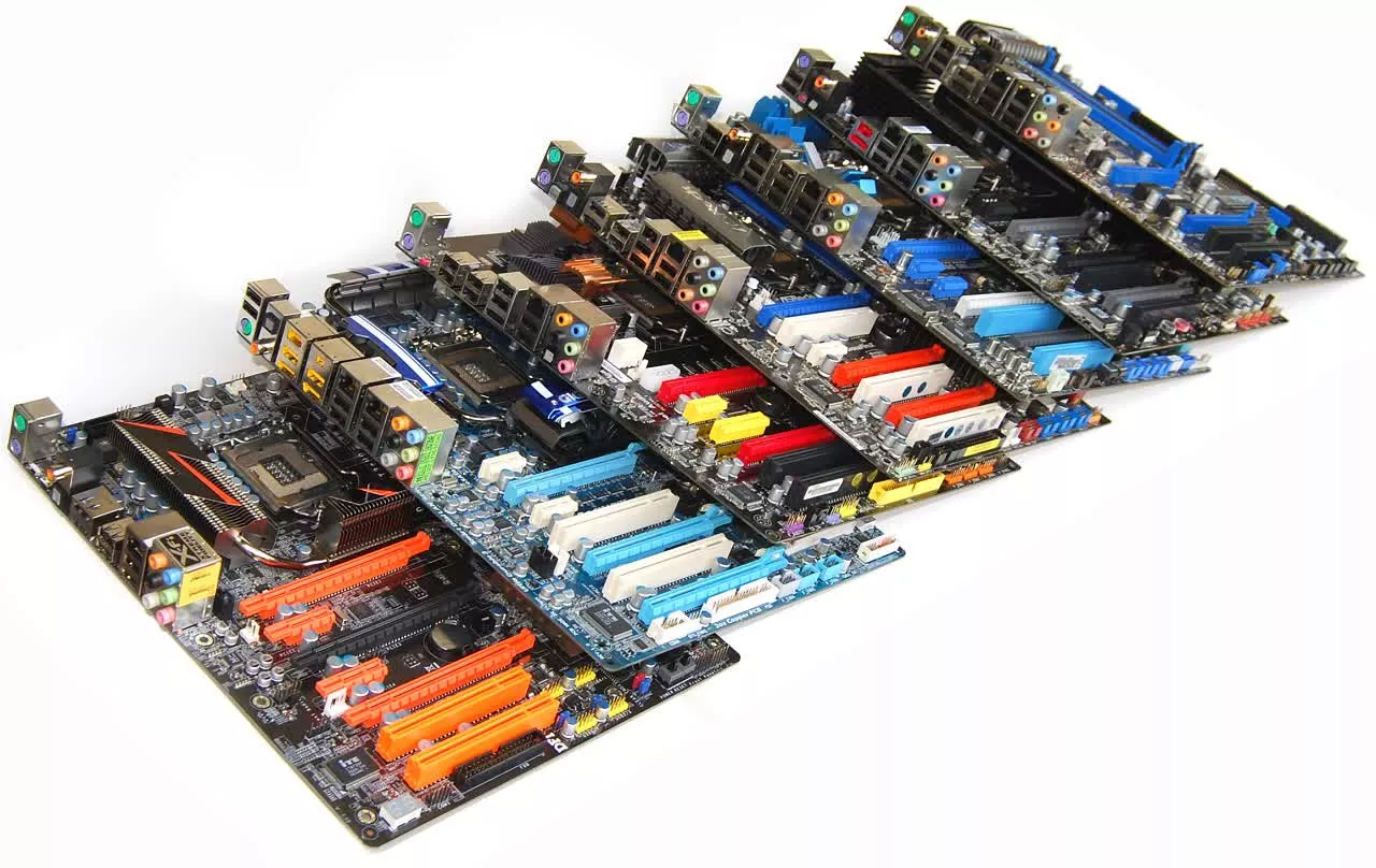
DFI has gone with a black and toxic orange color scheme which makes for a pretty cool effect as you will see in our various photos. The cooling design is also a bit more aggressive.

The chipset heatsink, located on the bottom right hand corner of the motherboard, measures 7 x 7cm and stands just 1 cm tall. It is connected by a heatpipe to a small array of fins in the middle of the board where the north bridge chip would be traditionally placed. This heatsink cools four small power chips and is also designed to improve the cooling properties of the entire system. Finally the biggest heatsink can be found behind the I/O panel cooling the board's power circuitry measuring 9cm long, 3cm wide and 3cm tall.
DFI has implemented a 6 + 1 phase digital PWM. Each phase PWM provides 30 - 40 watts of power, which is more than enough for the LGA1156 Core i5 and Core i7 processors. There is also an additional 2 phase PWM that is designed to deliver power to the GPU featured on-die in upcoming Clarkdale 32nm processors.
Looking at the overall layout it is clear that DFI has taken the time to make sure its LanParty DK P55-T3eH9 will provide gamers with all the features they need. Although the three PCI Express x16 slots are each only separated by a single slot, the primary and secondary ports which are likely the only two that will be used are three slots apart.

This provides maximum clearance for multi-GPU setups, improving air-flow and reducing temperatures. DFI is also well aware of the common DIMM slot/graphics card conflict and to avoid this problem they have pressed the DIMM slots hard up against the top of the board. There is at least a centimeter of clearance between long graphics cards and the DIMM slot clips, providing plenty of room to install and remove memory modules without first having to remove the graphics card.


The 24-pin ATX power connector is located on the top right hand corner of the motherboard where it is easy to access, and the eight onboard SATA ports have been mounted on a 90-degree angle to avoid any conflicts with long graphics cards. The CMOS battery is located between the PCIe x16 slots making it difficult to access but with the addition of a CMOS reset button on the I/O panel we can let this slide.

Speaking of the I/O panel here we have a pair of PS/2 ports, six audio jacks, optical and S/PDIF ports, eSATA, CMOS clear button, LAN port and just five USB 2.0 ports. There is also the mini USB port of course which as we explained is used to restore the motherboards BIOS. We were disappointed to find just five usable USB 2.0 ports on the I/O panel, though another eight can be installed using headers found on the motherboard.