Gigabyte P67A-UD7 – Design
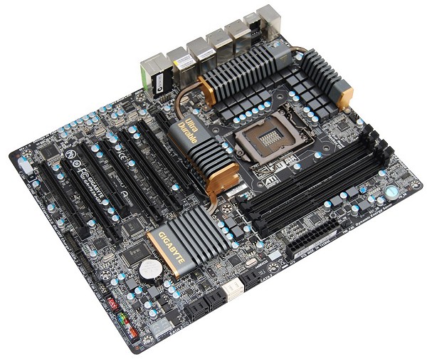
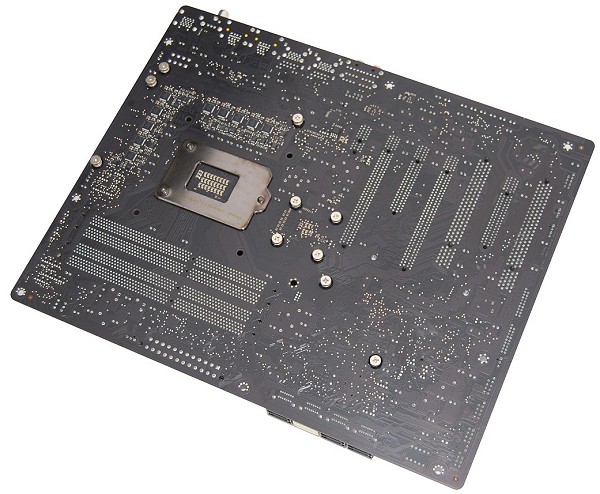
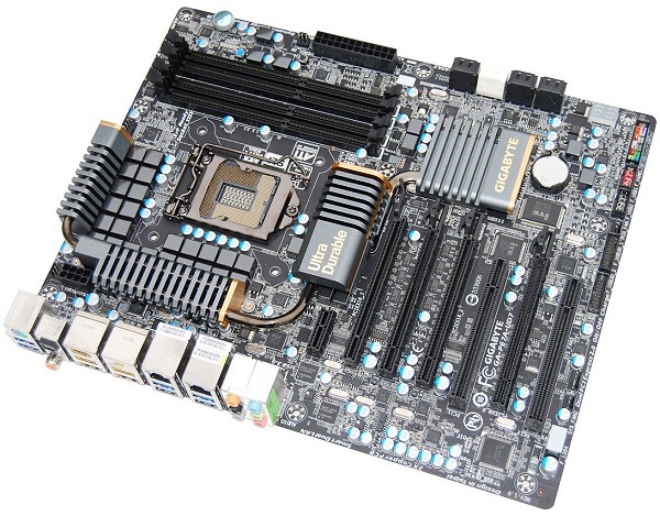
The matte black PCB gives the Gigabyte P67A-UD7 a unique look, as does its all-black component design. The layout is very solid and the only possible issue we can find is the placement of the DIMM slots and CPU socket which are a bit close.


The P67A-UD7 features a massive 24-phase power design which utilizes low core energy loss Ferrite Core Chokes as well as Low RDS(on) Driver-MOSFETs. These components supposedly handle a higher current load and offer better power efficiency along with lower operating temperatures. Each power phase of the motherboard has three main components: one choke, one capacitor and one MOSFET.

Gigabyte has also included their Dual Power Switching design which is intended to maximize the board's lifespan. When Dual Power Switching is activated, two sets of 12 power phases operate in tandem, automatically turning on one set of 12 phases and powering down the other 12. This allows the inactive set to rest and supposedly doubles the lifespan of the phases.

Gigabyte Dual Power Switching also has a unique feature that can automatically disable a group of 12 phases should it fail. With traditional motherboards, if one power phase fails, the board can't operate.
Cooling the 24-phase power design is a series of large heatsinks that are connected using a 6mm heatpipe. Like ECS and Asrock, Gigabyte has gone with gray or dark silver heatsinks that blend in nicely.

For those looking to add a few expansion cards, the P67A-UD7 provides a number of options with its four PCIe x16 slots, one PCIe x1 and two PCI slots. Unlike most Intel P67 motherboards, both the primary and secondary PCIe x16 slots provide the full x16 bandwidth when using two graphics cards. This is possible due to the implementation of the Nvidia NF200 chip.

The NF200 chip uses the native 8-lane configuration and doubles the bandwidth though it does not add PCIe lanes. Rather it splits the existing lanes and increases the bandwidth. Although theoretically this should create 32 lanes of PCIe bandwidth, Gigabyte has only allowed for a maximum of 3-way SLI. If they allowed 4-way SLI, each card would be limited to 8x bandwidth and this could hurt performance.
Given that the P67A-UD7 is designed for serious multi-GPU setups, the slot placement is important. Gigabyte has configured the board starting with a single PCIe x1 slot, followed by the primary PCIe x16 slot which has the full x16 bandwidth. Next is a PCIe x16 slot limited to x8 bandwidth which sits between the full x16 bandwidth primary and secondary slots. Then we have a PCI slot followed by another PCIe x16 slot with x8 bandwidth and then a final PCI slot.


The I/O panel features a PS/2 port, six USB 3.0 ports, two USB 2.0 ports, dual LAN ports, two eSATA ports, two FireWire ports, optical S/PDIF, coaxial S/PDIF and six audio jacks. The Gigabyte P67A-UD7 is very well equipped, offering more USB 3.0 ports than any other board in our roundup.