I have an oldish IBM-Deskstar model DTLA-307045. the power cord was stuck and unfortunately my finger slipped and knocked two of the tiny little components off the circuit board on the back. What shall I do??? can I get a new board to go on the back? or shall I attmept to soulder them back on? has important information on it aswell as the kind I dont want other people seeing (if you know what I mean).
You are using an out of date browser. It may not display this or other websites correctly.
You should upgrade or use an alternative browser.
You should upgrade or use an alternative browser.
External circuitry damaged on hard drive
- Thread starter greeny12m
- Start date
- Status
- Not open for further replies.
Mictlantecuhtli
Posts: 4,049 +13
If your hands are steady enough, and you know how to solder that kind of things, I don't see why soldering wouldn't work, unless the drive was in use when this happened and it damaged something else too.
The circuits are specific for the drive model. You could get another board but you'd either have to find another drive of the same model or send it away to get repaired.
If you do decide to solder the components back on make sure you are using a fine tip and don't hold the iron on the board for any more than 2 seconds otherwise you may damage the circuit board.
To make it easier you could use a small amount of super glue to hold the components in place, just don't get it on the solder pads.
Also, if the components (looks like they may be resistors) are different values, make sure you put them back in the right spot.
Samstoned
Posts: 1,009 +0
see if you can find the schematic of the board and I have done this before
use a very small tipped gun heat at 850 f 4 to 5 secs would not normal hurt it
watersoluble flux and no other or you will damage board
boards are multi layer and acid flux can not be cleaned from wicking into the layers
resisters are easy a diode or cap is tougher as you have to mount in right direction
don't hold the iron on the board for any more than 2 seconds otherwise you may damage the circuit board.
To make it easier you could use a small amount of super glue to hold the components in place, just don't get it on the solder pads
I agree whith the other things you said, but disagree with this almost entirely.
The two second limit is ficticious, especially with a very fine tip. I do agree that too much heat will damage the circuit board though. More to the point, to much heat will damage an SMT component!
You can leave the heat on the board for a reasonable length of time, but not so long that you loose the pad, and those pads for SMT compoents are VERY easy to loose sometimes. you should apply the heat to the component only for a short a time as possible for the solder to flow around it and stick. I deally, the solder should form a concave surface rising as a slope from the pad to the component. If there is to little solder, it doesn't conduct properly, and too much solder runs the risk of splashes, a weak (hollow) joint, or in rare circumstances, (bearing in mind that many electronic boards are tested and then calibrated after these components are stuck on) a lower resistance.
When soldering these things, you hold them reasonably gently with a tweezers in the center of the component, making absolutely sure that they are flat to the board. If necessary, you need to re-work the pad to get any existing solder off it. For speed, it is best to use a soft solder (60% lead, or higher). whilst holding the component down, heat the pad a little, then lift the iron (a fine tipped iron that is, at a lowis temp wher possible) without scraping the pad and immediately apply the iron to both the pad and wall of the component.as you do this, provided your iron is warm enough, add a small amont of solder and remove the solder, then the iron, all in one smooth motion if possible, all the time holding that component close to the board. You can then put the tweezers down, and solder the other side. I'm afraid it's a three hand job with these things.
By the look of the image, those components are most likely resistors, but could also be capacitors.
The whole thing should take about 3 seconds per component if you're being careful per component side. Fluxwill help the solder flow better, but as Samstoned said, NO acid flux! And whatever you do, make sure you put the right component in the right place, because those pads DON'T like being reworked more than a few times. I used to do it for a living to varying standards (either military, or aviation. Aviation standard sucked!) Surface Mount Technology wasn't designed for hand soldering, but it can be done if your careful.
One last caution. If you use a solder sucker to remove the excess before or during the operation, whatever you do, don't hit a pad while using it. those things seem almost guarenteed to lift the older pad if you hold them to close, or hit the board with the recoil.
It's not as hard as I've just made it sound, I've just gone into detail, butIt is very important to be careful.
Sorry for being ignorant but.....
What is flux? is it like glue? is it expensive?
and when you say the pad what exactly are you refering to?
can capacitors be soldered backwards?
also would it be dangerour to my data if i tried to use it with these components missing? i would only need to read data from it for an hour or so.
Thanks for the enormous response, my other posts havent been so sucessful")
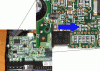
ive attached pics of the components in question.
What is flux? is it like glue? is it expensive?
and when you say the pad what exactly are you refering to?
can capacitors be soldered backwards?
also would it be dangerour to my data if i tried to use it with these components missing? i would only need to read data from it for an hour or so.
Thanks for the enormous response, my other posts havent been so sucessful
ive attached pics of the components in question.
The pad is the small silver area on the board on which the solder stick when you place the component on it.
Flux, well, easiest way to describe it is that it's like a cleaning fluid and catalyst, making the solder flow better. It scours the surface of the solder. It's available in liguid form, or a pot of resin-like stuff for cleaning and tipping the iron, and also as a grease-like form. You would probably want the liquid form if possible.
Some capacitors can be soldered backwards. Some cannot. It depends on whether the capacitors in question are polarised or not. If polarised, the component is marked and must be added onto the board facing the corect way.
The component you are missing will most likely either be black with numbers on them (resistors) or ceramic in a sort of browny red colour (capacitors)This rule isn't firm though. there are a few exceptions. There are other colours and the like, but these two are the most commont for the rectangular component type.
My GUESS is that the components you're missing, according to the pcture, are non-polarised capacitors. It's very difficult to be sure, but from their shape and colour, I'd guess that's what they are, unless they have any markings on the otherside to the contrary.
Samstoned
Posts: 1,009 +0
sec. look I do believe you are right Spikethose are caps
and should not have a polarity (I'm going blind).I still feel better with schimatic in my hands.
only reason I differ to 6 seconds on time is just what you said about the copper pads coming loose
SMT was designed to be soldered with very hot, very fast radiant heat called reflow ovens.
looks like (if parts are still good ) 5 min. job
Well, anything is possible. I have no idea what those components are responsible for on the board. There's just no way to dell unless you have the board schematic, accompanying notes, and one hell of a good understanding and level of knowledge of electronics.
I'm afraid that as far as I can tell personally, it really is just a case of try what you feel best about trying, and do so at your own risk.
I'm afraid that as far as I can tell personally, it really is just a case of try what you feel best about trying, and do so at your own risk.
it worked
just an update for you guys, i know its been a while but thought u might like to know: i asked my brother to do it, he has always bn gd at that sort of stuff and everything works fine, not sure wether theyre unnecessary components or what but im still using the drive and its as good as new.
just an update for you guys, i know its been a while but thought u might like to know: i asked my brother to do it, he has always bn gd at that sort of stuff and everything works fine, not sure wether theyre unnecessary components or what but im still using the drive and its as good as new.
- Status
- Not open for further replies.
Similar threads
- Replies
- 1
- Views
- 10K
D
Latest posts
-
 US TikTok ban could begin next year as Biden signs law, but legal battle looms
- GodisanAtheist replied
-
 Upgraded 4K Chromecast with Google TV set to launch soon with improved hardware
- hahahanoobs replied
-
 Nintendo DMCA lawyers shut down everything Mario on Garry's Mod
- Uncle Al replied
-
BlizzGone: Blizzard cancels 2024 convention but promises an eventual return
- GodisanAtheist replied
-
TechSpot is dedicated to computer enthusiasts and power users.
Ask a question and give support.
Join the community here, it only takes a minute.